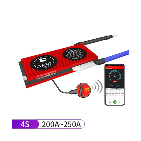
Smart BMS 4S 200A-250A LiFePO4 For 4S 12V LiFePO4 Battery
Smart Bms 4S 200A-250A LiFePO4 With GPS/CAN/BLUETOOTH/BATTERY BOARD For 4S 12V LiFePO4 Battery
- Category: Battery Management System
- Tag: Battery Management System BMS
Smart BMS 4S 200A-250A LiFePO4 With GPS/CAN/BLUETOOTH/BATTERY BOARD For 4S 12V LiFePO4 Battery
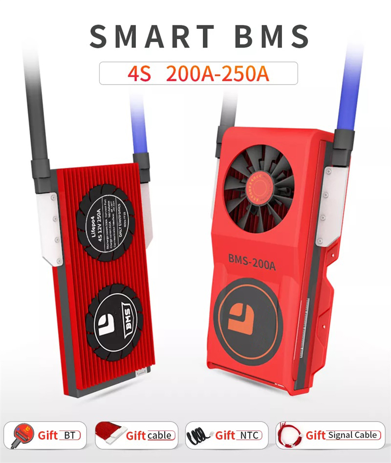
Product Summary
1. Professional high current wiring design & workmanship, thus can withstand the shock of high current
2. Using fully enclosed heat-dissipating glue and a double-sided heat dissipation design, heat is dissipated in time, and the heat dissipation effect is better than others.
3. Dustproof, shockproof, anti-squeezing, and other protective functions
4. Complete overcharge, over-discharge, over current, short circuit, and equalization functions
FULL INTELLIGENT FUNCTION
PRODUCT PARAMETERS
(4S 200A-250A)
No | Description | Specification | Remarks | ||
1 | Discharge | Continue discharge current | 200A | 250A | |
2 | Charge | Charge voltage | 14.6V | ||
Charge current | 100A | 125A | |||
3 | Over charge protection | Over charge detect voltage | 3.75±0.05V | ||
Over charge protection delay | 1S | ||||
Over charge release voltage | 3.65±0.05V | ||||
4 | Balance | Balance detect voltage | 3.2V | ||
Balance current | 30±5mA | ||||
Balance opening condition | 1. On a charge 2. Achieve balance detect voltage 3. Achieve 50mv | ||||
5 | Over discharge protection | Over discharge detect | 2.2±0.01V | ||
Over discharge detect delay | 1S | ||||
Over discharge release voltage | 2.3±0.01V | ||||
6 | Charging over current protection | Charging over current protection current | 300±30A | 375±38A | |
Over Charge current detect delay | 1S | ||||
Over Charge current protection release condition | Off load | ||||
7 | Discharge over current protection | Discharge over current protection current | 300±30A | 375±38A | Can set as required |
Over discharge current detect delay | 1S | Can set as required | |||
Over discharge current protection release condition | Off load | ||||
8 | Short Circuit protection condition | Short circuit of external load | |||
Short circuit detect delay | 320uS | ||||
Short circuit protection release | Off load | ||||
9 | Temp Protect | Charge Temperature protection degrees | -40~65℃ | Recover-35℃ Recover 60℃ | |
discharge Temperature protection degrees | -40~70℃ | Recover-35℃ Recover 65℃ | |||
Release Condition of temperature protection | Recovery temperature reached and load disconnected | ||||
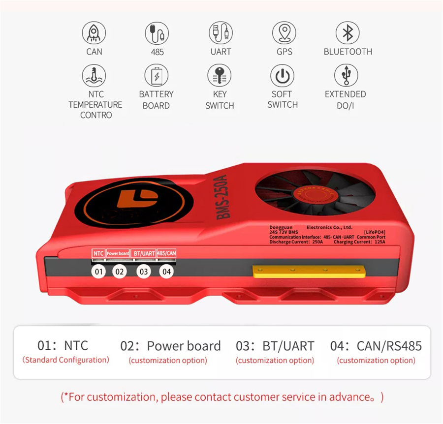
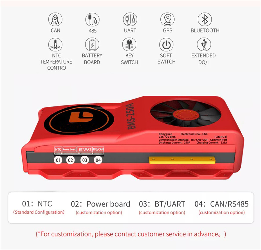
10 | Means of communication | UART/ BT/CAN/RS485 Customization Option | |||
11 | Inner Resistance | Main Circuit Conduct Inner resistance | <20mΩ | ||
12 | Self Consumption | Working current | 20mA | ||
Sleeping current | 800uA | ||||
13 | Working Temp | Temp range | -20~70℃ | ||
14 | Storing Temp1 | Temp range | -40~80℃ | ||
BMS WIRE DIAGRAM
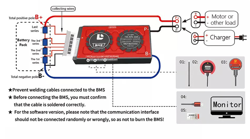
Precautions for smart BMS:
1. The connection sequence of the smart BMS
The wiring sequence of the cable is the same as the hardware board. After confirming that the cable is soldered correctly, and the accessories that come with the product (such as: temperature control standard/power board option/Bluetooth option/GPS option/display option/custom communication Interface optional)
Install on the BMS, and then plug the cable into the BMS socket; the blue B-wire on the BMS is connected to the total negative electrode of the battery, and the black P-wire is connected to the negative electrode of the charge and discharge.
2. The BMS needs to be activated for the first use
Method 1: Activate the Power display panel, there is an activation button on the Power display panel.
Method 2: Charge activation.
Three, parameter modification
The number of strings of the BMS and the BMS parameters (Li-ion BMS, LiFePO4 BMS, LTO BMS) have default values when they leave the factory, but the capacity of the battery pack needs to be set according to the actual capacity AH of the battery pack. If the capacity AH is not correct Set, the percentage of remaining power will be inaccurate. Other protection parameters can also be set according to the customer's needs (It is not recommended to modify the parameters casually).
