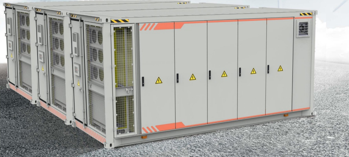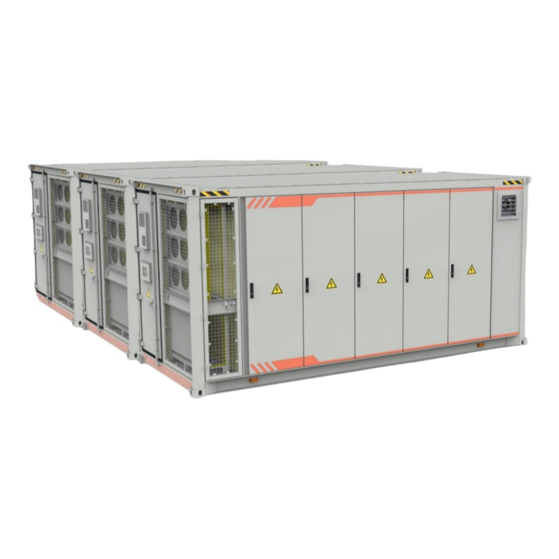
20ft 2MWh Outdoor Liquid-Cooling Energy Storage Container for BESS System
The 20ft 2MWh outdoor liquid cooled energy storage container is composed of 7 1P416S, 1331.3V 280Ah battery racks with BMS, which has the characteristics of high power and long life.
- Category: Energy storage system
- Tag: Energy storage system
20ft 2MWh liquid-cooling energy storage system adopts the outdoor container BESS system, which contains LFP battery: NESPseries, intelligent battery management systemand the group technology. We can supply safe, reliable, stable power supply solutions, to provide comprehensive highly quality energy.
In DC section, one battery bank is made up with certain number of racks in accordance with the system configuration and normally one battery bank connectsto one PCS. Several combinations of PCS and battery system establish the whole BESS.
BESS Topological Drawing
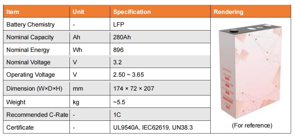
Battery System Design-280Ah LFP battery
Battery Cell
3.2V 280Ah lifepo4 battery Cell: efficient, safe, and reliable
Specifications
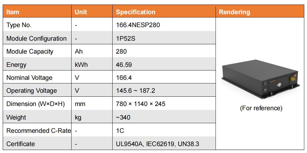
Battery Module
Independent battery module design: One battery module consists of a number of cells in a manner of 1P52S, with rated voltage of 166.4V and rated capacity of 280Ah.
Specifications
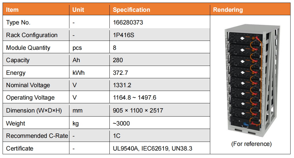
Battery Rack
Each battery rack contains 8 modules and 1 control box. A number of modules and control box are connected in series through electrical connectors, delivers high voltage up to 1331.2V in rated voltage and 280Ah in rated capacity.
Specifications
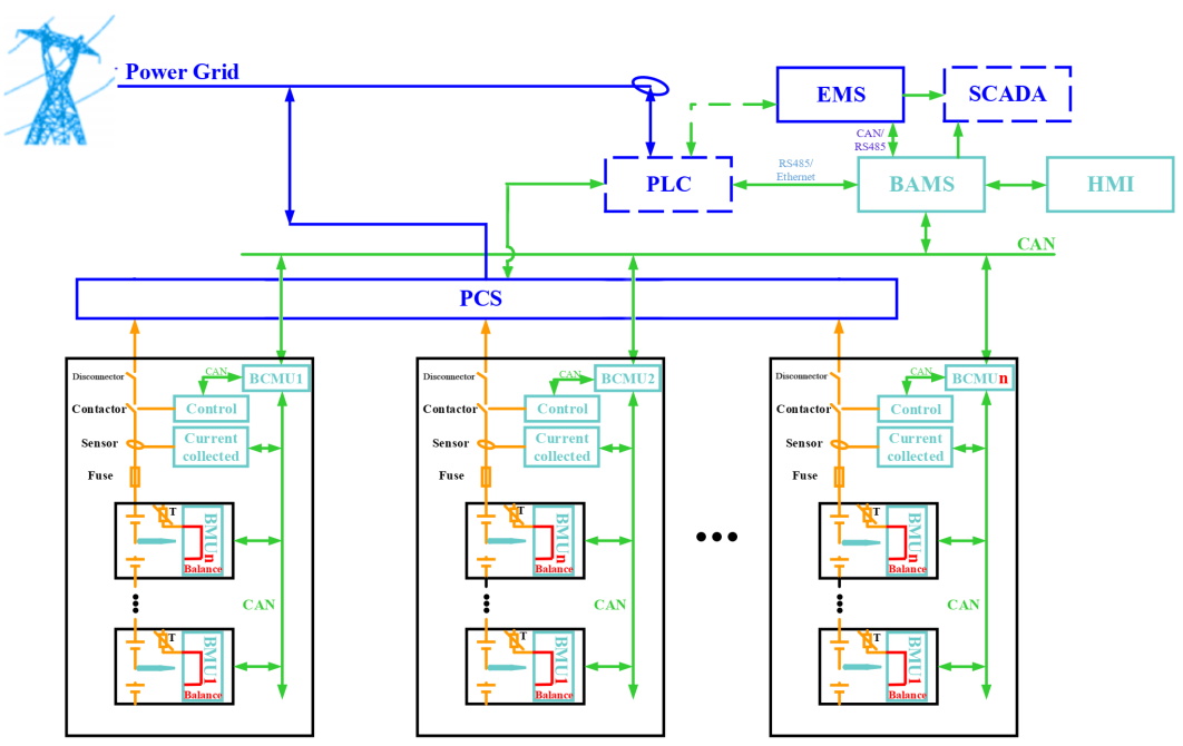
Battery Management System (BMS)
For three-level architecture, BMS system is composed of module level BMU, rack level BCMU and bank level BAMS. The overall control and communication diagram is shown as below:
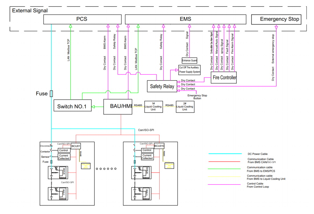
BMS Communication Diagram (For reference)
Battery Container
Composition: A 20ft ISO 2MWh container consists of 7 strings of 1331.2V 280Ah battery racks with BMS
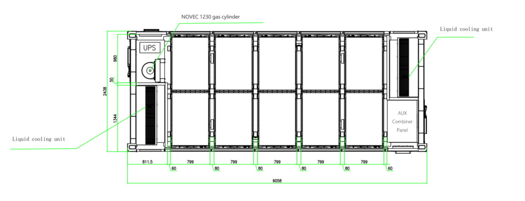
Battery Container Layout (For reference)
Auxiliary System Design
AUX Combiner Panel
Auxiliary power supply
a) Power source of Liquid cooling unit, FSS, Lighting, BMS, etc.;
b) With UPS minimum 15 minutes time as backup power supply;
c) Flexible power resource input support: 380/400/480Vac/50/60Hz 3P4L (The type of
auxiliary resource shall be confirmed by the Client before the contract);
d) Protection function with main circuit breaker and dual E-stop circuit systems
DC combiner panel
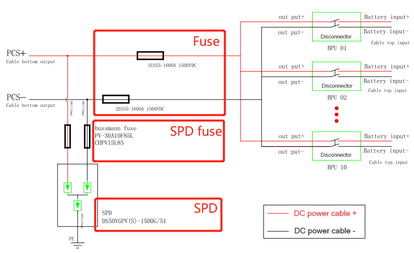
DC Combiner Panel Connection Diagram (For reference)
Thermal Management System-Liquid-Cooling
The enclosure has a multi-stage cooling system for the battery, consisting of three levels:
(1) Master Pipe: Located at the top, connected to the cooling unit.
(2) Secondary Pipe: Distributes cooling to each rack stage.
(3) Branch Pipes: Directly cool individual modules.
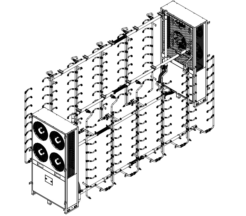
Liquid Cooling Pipe Layout (For reference)
Fire Suppression and Alarm System
The fire suppression system includes an automatic fire alarm, gas fire extinguishing, gas detection, exhaust fan, and sprinklers. It features control logic for gas detection, fire alarms, and manual/automatic modes for emergency response.