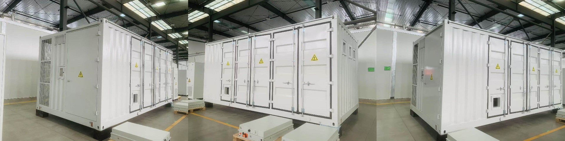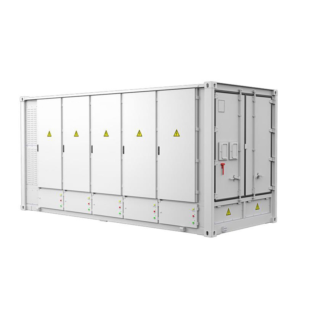
EnerC 0.5P Energy Storage Container containerized energy storage system
EnerC's liquid-cooled battery container: a high-density, integrated system with BMS, FSS, TMS, and auxiliary distribution
- Category: Energy storage system
- Tag: enerC 0.5P energy storage container
EnerC liquid-cooled energy storage battery containerized energy storage system is an integrated high energy density system, which is in consisting of a battery rack system, battery management system (BMS), fire suppression system (FSS), thermal management system (TMS) and auxiliary distribution system.
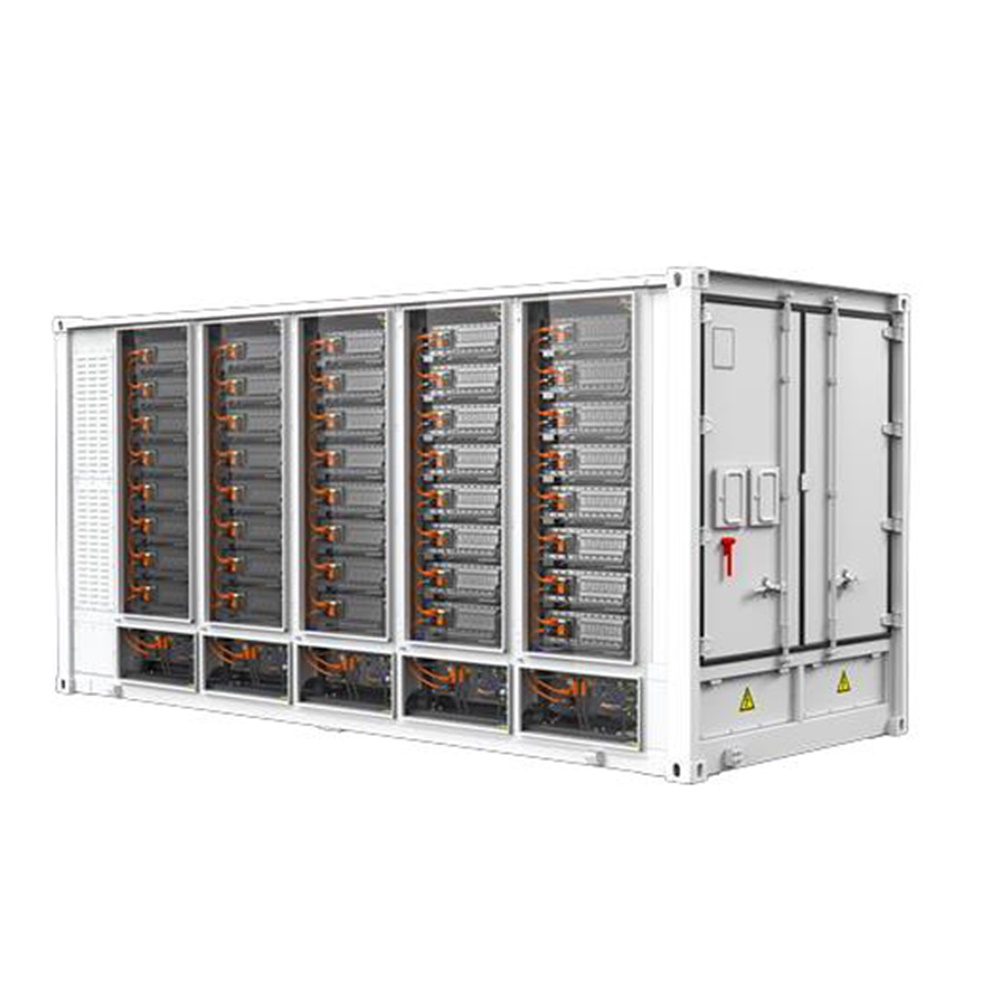
Components of EnerC liquid-cooled energy storage container
Battery Racks, BMS, TMS, FSS, and Auxiliary distribution system
The battery system is composed of 10 battery racks in parallel.
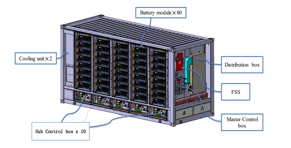
The battery system is composed of 10 battery racks in parallel. Each battery rack contains 8 battery modules by series connection, each battery module is composed of 52 battery cells in series connection also, so each rack contains 416 battery cells. Totally, EnerC liquid-cooled container’s configuration is 10P416S.
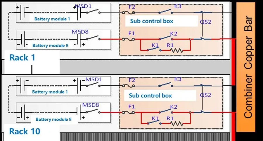
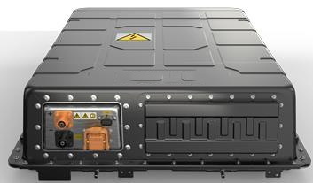
A total of 52 pieces of lithium iron cells (280Ah/3.2V) in series connection are used for every battery module. For safety protection, an internal high-speed DC fuse is included, and a removable MSD switch can cut off the high-voltage connection during the transportation process.
Product Specification
Item | Specification |
Configuration | 10P416S |
Rated Energy | 3727.36kWh |
Rated Voltage | 1331.2VDC |
Voltage Range | 1164.8~1497.6VDC |
Charging Current (0.5 P) | Rated:1400A |
Maximum:1600A | |
Charging Power (0.5P) | Rated:1863.68kW |
Discharging Current (0.5P) | Rated:1400A |
Maximum:1600A | |
Discharging Power (0.5P) | Rated:1863.68kW |
Auxiliary power supply (0.5P) | Voltage range:3AC 380…480V |
Power: Max. 36.0 kW (Including BMS & Chiller consumption) | |
Operating Ambient Temperature | Charge:-25 ℃ to +55 ℃ |
Charge:-25 ℃ to +55 ℃ | |
Environment condition | Storage Temperature:-30℃ to +60 ℃ |
Application altitude:≤2000m | |
Size | 2896mm(H)*2462mm(W)*6058mm(D) |
Color | RAL7042 |
Weight | ~35t |
IP Level | IP55 (Battery Room) IPX5 (Electrical Room) IPX6(Cooling unit) |
Cooling mode | Liquid Cooling |
Communication protocol Communication port | CAN, TCP/IP |
RS485, Fiber ST | |
Power connection | Cable lug: External: 6 x M12 single hole or double hole/phase Internal: 10 x M8 single hole or double hole/phase |
Communication connection | Fast plug |
Aux Power connection | Terminal |
Coolant | 50% Ethylene glycol aqueous solution |
Fulfill standard Cell | UN38.3 |
UL1973 | |
GB36276 | |
IEC62619 | |
UL9540A | |
Fulfill standard Container | IEC62477 |
IEC62619 | |
IEC 62933-5-2 | |
IEC63056 | |
UL1973 | |
UL9540A | |
IEC 61000-4/ IEC 61000-6 |
1) The actual power consumption depends on the ambient temperature and Charge/Discharge working profile.
2) If cold starting for battery cell temperature below 0 ℃, a pre-heating process via chiller is necessary, otherwise it’s not allowed to charge.
3) If the battery cell temperature is above 25 ℃ without any cooling during storage, the SOH degradation will be sped up, separate SOH degradation evaluation needs to be done case by case according to average storage temperature.
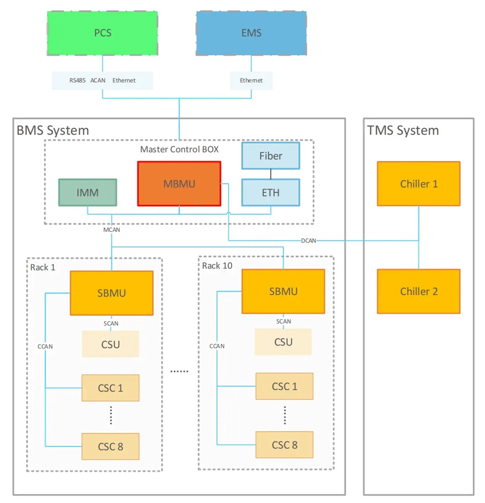
BMS system overview
BMS is used in conjunction with the ESS energy storage system, which can monitor the battery voltage, current, temperature, managing energy absorption and release, thermal management, low voltage power supply, high voltage security monitoring, fault diagnosis and management, external communication with PCS and EMS, ensure the stable operation of the energy storage system.
The BMS system is composed of 1 unit of MBMU, 1 unit of IMM, 1 unit of ETH, 10 units of SBMUs, and 80 units of CSCs.