

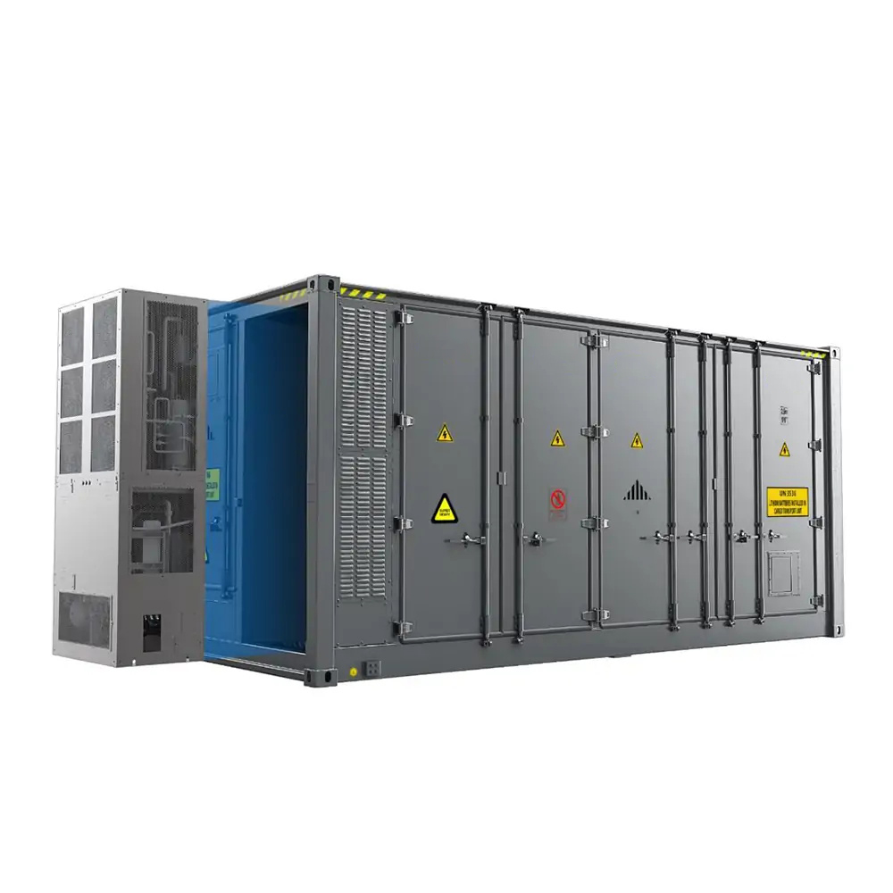
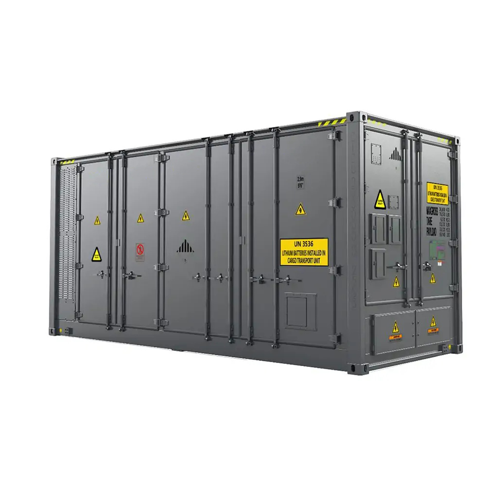
CATL EnerC+ 306 4MWH Battery Energy Storage System Container
The CATL EnerC+ container is a modular integrated product with rechargeable lithium-ion batteries. It offers high energy density, long service life, and efficient energy release for over 2 hours.
- Category: Energy storage system
- Tag: bess container
The CATL EnerC+ 4MWH container is a modular fully integrated product, consisting of rechargeable lithium-ion batteries, with the characteristics of high energy density, long service life, and high efficiency. It can provide stable energy release for over 2h when the batteries are fully charged. The EnerC+ Energy Storage product is capable of various on-grid applications, such as frequency regulation, voltage support, arbitrage, peak shaving and valley filling, and demand response. In addition, the EnerC+ container can also be used in the black start, backup energy, congestion management, microgrid, or other off-grid scenarios.

The EnerC+ container is a battery energy storage system (BESS) that has four main components: batteries, battery management systems (BMS), fire suppression systems (FSS), and thermal management systems (TMS). These components work together to ensure the safe and efficient operation of the container.
Battery
The capacity of the cell is 306Ah, with 2P52S cells integrated in one module, 8 modules integrated into one rack, and 5 racks integrated into one container. The core of the energy storage system, the battery releases and stores energy
BMS
BMS adopts the distributed scheme, through the three-level (CSC--SBMU--MBMU) architecture to control the BESS, to ensure the stable operation of the energy storage system. It can manage energy absorption and release, the thermal management system, and low voltage power supply according to the detected information: battery voltage, current, and temperature. It can monitor high voltage DC/AC security, and diagnosis and analyze faults according to information from various detectors and dry-contacts. And it can keep communication with PCS and EMS through CAN. The BMS is the most important control unit of the EnerC+ container. The BMS possesses the UPS to keep normal function when facing a temporary out of power.
FSS
FSS consists of smoke detectors, heat detectors (optional), H2 detectors, the fire control panel, aerosol, the dry pipe(optional), the smoke exhaust ventilation system, and the UPS. FSS undertakes functions: monitor the thermal run-away risks of the container through the detectors, extinguish the thermal run-away, especially the flame fire, and control the loss to a minimum. The control panel will control and record information for the fire suppression system. The FSS is independent of any other system and it is the security guard of the EnerC+ container.
TMS
TMS consists of one powerful chiller, the PTC heater, and the liquid cooling pipe distributed in each battery module. The TMS will control and keep the temperature of the battery within a reasonable range. The battery will work at the best state and reach the longest life under the thermal management system.
Advantages of EnerC+ container
1) Standard design.
The 20ft design is very convenient for transportation. The standard design can be installed one-stop.
2) New generation Cell.
EnerC+ container integrates the LFP 306Ah cells from CATL, with more capacity, slow degradation, longer service life, and higher efficiency.
3) High integrated.
The cell-to-pack and modular design will increase significantly the energy density of the same area. The system is highly integrated, and the area energy density is over 270 kWh/m2.
4) Extreme safety.
The system supports three levels of safety:
Firstly, the cell safety, the highly stable lithium iron phosphate is used in the EnerC+ container. LFP is a kind of safety material, especially for the BESS.
Secondly, the electrical safety:
a) E-Stop design;
b)multiple fuse protection design;
c) insulation monitor
voltage monitor;
d) multi-channel isolation design;
e) lightning protection design.
Thirdly, in the fire protection design
CATL has a four-level fire control strategy. The first level is the alarm. The second level is ventilation and smoke exhaust to prevent deflagration. The third level is aerosol to extinguish the initial fire, and the fourth level is the dry pipe sprinkle fire protection to prevent fire spread.
5) Adaptive thermal management.
EnerC+ integrated single-cluster water pump, temperature control strategy automatically adjusted with battery status, prolonging battery life.
6) Easy extension.
It is very convenient for the augmentation of containers or racks. Furthermore, the EnerC+ supports one PCS connected to 2 containers; this will decrease the covered area significantly.
7) Independent UPS.
EnerC+ container has integrated two UPS systems, one is for the FSS monitoring system whose available capacity is 24 hours, and another one is for BMS whose available capacity is 20 minutes
Specifications
Power and Energy of EnerC+ DC Side Data | |
Product Model | C02306P05L01 |
P-Rate | 0.5P |
Cell type | LFP |
Cell capacity | 306Ah |
Cell Voltage range | 2.5-3.65V |
Cell rated Energy | 979.2Wh |
Configuration | 5P2P416S |
Rated Energy | 4073.47kWh |
Rated Voltage | 1331.2VDC |
Voltage Range | 1040 ~ 1500VDC |
Rated Charging Current | 1530A |
Maximum Charging Current | 1883A |
Rated Charging Power | 2036.73kW |
Rated Discharging Current | 1530A |
Maximum Discharging Current | 1883A |
Rated Discharging Power | 2036.73kW |
Auxiliary Power & Communication | |||
Product Model | C02306P05L01 | Remark | |
P-Rate | 0.5P | ||
Relative Humidity | 0 ~ 95 % (non- condensing) | ||
Degree of Anti-corrosion of Battery Unit | C4, (optional C5) | ||
Seismic Level | IEEE 693-2018 Moderate design level | ||
Auxiliary Power 1 | Voltage Range | 3AC+N+PE 380V~480V ±10% ,50/60HZ | |
Power | Max. 31.01kW | For reference | |
Inrush Current | ≤65A,< 5S | ||
Auxiliary Power 2 | Voltage Range | 1AC230(L+N) or 2AC(380-480) | |
Power | Max. 0.8kW (Continuous) | ||
Inrush Current | 5A | ||
UPS |
Capacity |
DC24V. 7Ah capacity.@25℃ | The UPS is only used to supply power to BMS components. The UPS is included in the Aux power supply |
Communication Protocol | CAN, Modbus/TCP | ||
Mechanical Data | |||
Product Model | C02306P05L01 | Remark | |
Transportation | Land or sea transportation | ||
Battery Management System(BMS)
BMS Overview
BMS is used in energy storage systems, which can monitor the battery voltage, current, and temperature, manage energy absorption and release, thermal management, low voltage power supply, high voltage security monitoring, fault diagnosis and management, external communication with EMS and ensure the stable operation of the energy storage system.
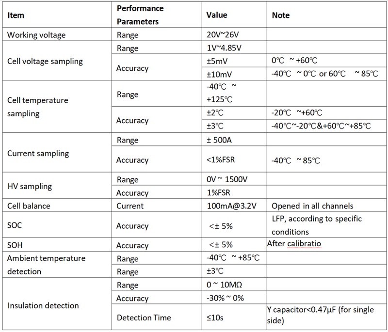
BMS Function
The detailed information of BMS can be seen in Table 6. The parameters include Cell voltage sampling, Cell temperature sampling, Current sampling, HV sampling, Ambient temperature detection, Insulation detection, and other important parameters.
Fire Suppression System(FSS)
FSS Overview
As an outdoor non-walk-in battery energy storage system, EnerC + provides a perfect set of fire suppression system solutions with detection, explosion control, and fire extinguishing functions. The fire extinguishing control strategy is divided into four levels:
The first level is an alarm warning;
The second level, ventilation, and smoke exhaust to prevent deflagration;
In the third level, the aerosol is released to extinguish the initial fire;
Fourth level, dry pipe spraying to control the spread of fire.
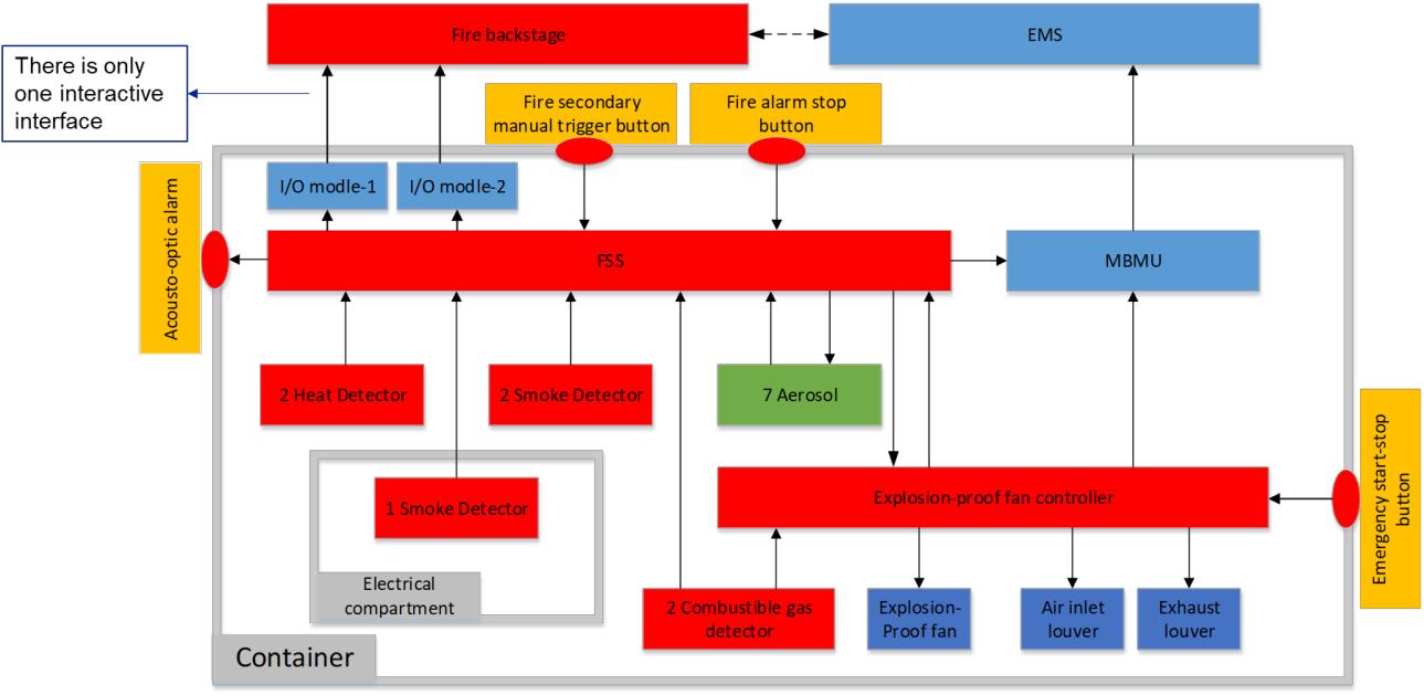
FSS Function
The fire suppression system is divided into three parts: a detection system, an explosion-proof system, and a fire extinguishing system. The information on the interactive interface is shown in the following:
Thermal Management System(TMS)
TMS Overview
The TMS system of EnerC+ is liquid cooling, whose main function is to maintain the temperature of the battery system to an allowable operating temperature range. Thus, the battery shall work at the best conditions, adsorb and release the maximum energy, slow degradation of the SOH, and maintain the longest life.
The Thermal management system is composed of a high-efficiency liquid cooling unit, the liquid cooling pipe under the bottom of the battery, and the PTC heater. The TMS works under the control of BMS. BMS sends the start-up or shut-down signals to the cooling unit, then the cooling unit and the PTC heater will work together to change the temperature of circulating coolant liquid for heat exchange in the cooling pipe. The circulating liquid will exchange the heat with the battery through the pipe. Thus, the temperature of the battery will increase or decrease into the appropriate range.
For example, the cooling unit will be started if the BMS detects the battery temperature over the setting value. The cooling mode will be activated to decrease the temperature of the circulating liquid until reaching the setting value. When the BMS detects the battery temperature less than the setting value, the heat mode will be activated to increase the temperature of the circulating liquid until the setting value. Detailed information will be described below.
TMS architecture
